GNS3: Build and configure a CCNA PPP lab using GNS3, dynamips, and vpcs
Cisco’s Packet Tracer works for very basic labs, but it has so many irritating small things that are missing, that it causes more frustration than nice experiences if doing anything involving anything more than the absoulte basic configurations. It does have one strong point, and it is CPU and memory usage, compared to emulating router hardware, which this article will be mainly about.
The strong point of Packet Tracer is it’s design mode, basically one can build larger topologies, and atleast look at them, and simulate basic network functionality, but if one wants to learn to configure and handle real equipment, using real equipment is the only way. But, in many cases to play with certain protocols or functions, emulating the hardware works as good, or better, if you don’t have a decent rack with hardware in your home.
I will try to give a decent how-to styled instruction how to accomplish this using GNS3 (under Windows since that’s what this box runs at the moment).
What we need:
- GNS3 (the all-in-one Windows installer including Dynamips, Pemu and WinPCAP if under Windows)
- IOS images
- vpcs (Virtual PC Simulator)
- PuTTY (or the telnet client of your choice on the OS you run)
Preparation
Download and install GNS3.
Download and unpack vpcs.
The first thing you should do is following the documentation of GNS3, to set up a router with an IOS image, and set it’s IDLE PC value. Read the “Creating the Simplest Topology” section of the PDF linked above to learn how to accomplish that. Also remember to add a WIC-2T card to the router, or make sure it has two serial interfaces.
Building the topology in GNS3
When you have a router set up and configured with an IDLE PC value that doesn’t consume all your processor cycles, continue building the topology in GNS3, as follows.
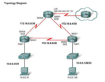
This is the topology that we will use, as shown in the CCNA4 curriculum lab manual.
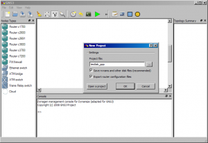
When starting GNS3 we have an empty working space. Upon start we are asked to either name, and create a new project, or open an existing one. Choose an appropriate name, like “testlab_ppp”, remember to check the “Export router configuration files” checkbox.
Adding devices
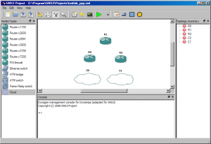
The first thing we do is add the three routers, using a model, with an IOS image that you have already configured. I use the “Router c2600” with a “c2600-ipbasek9-mz.124-17.bin” IOS image. After adding the three routers, add two Cloud units, they will be our simulated PC:s. We skip the switches completely, as they are only there to make it possible to not use any crossover cables in this (and many other) labs. In GNS3 cabletype is insignificant, we will therefor connect the simulated PC:s directly to the routers instead. (But do remember and really note, “Now I connect this to that using a crossover cable.” (even if you really don’t see it, in GNS3) when you build the topology, to get it in your head properly and not get bad habits.)
Creating the serial links
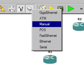
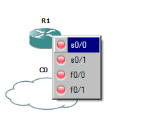
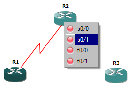
Now we create the serial links, by clicking on the “Add a link” button, and choosing “Manual”, then when clicking on R1, we choose s0/0 from the list of interfaces, then click on R2, selecting the interface we want to connect to, in this case s0/1. Create the other two serial connections in the same way.
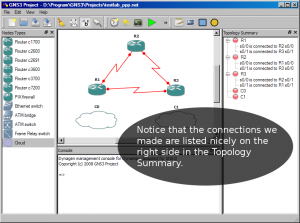
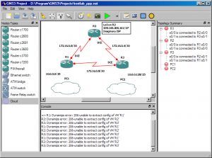
Now we have the routers connected in a triangle, using their serial interfaces. The Topology Summary on the right side gives a good overview which interface is connected to which, on which device. Before continuing, we can rename the devices, and adding some textlabels to the topology, so it looks something like the screenshot below.
Configuring the Cloud devices and Virtual PC Simulator
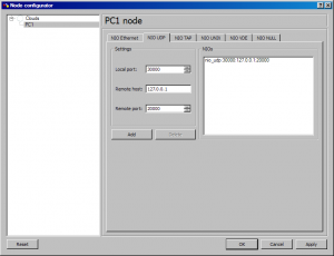
The default ports for vpcs are, listening: UDP 20000 and up, remote (dynamips’ end): UDP 30000 and up. Up to 9 PCs can be simulated by vpcs, we will use two this time, the ports we will use are then 20000 and 30000, and 20001 and 30001. The first thing we need to do to be able to connect to vpcs is to configure the two Cloud devices. To do that we right click on the first one, PC1, and choose “Configure”. Then the “NIO UDP” tab, because that is what we will use to communicate with our virtual PCs, two UDP ports, and since we are running both dynamips and vpcs on the localhost, we will connect to the port on host 127.0.0.1.
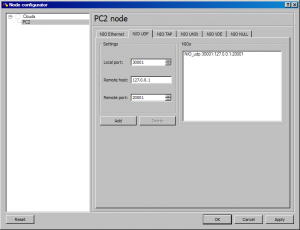
Then we do the same thing with PC2, which will use local port 30001, host 127.0.0.1, and remote port 20001.
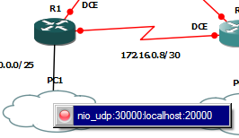
When both PC clouds are configured with their corresponding UDP ports, add a link between the routers and the clouds, in our case between fa0/1 on each router, to the cloud underneath them.
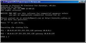
Next step is configuring vpcs and starting it. The config file is called startup.vpc and is located in the directory where you unpacked vpsc. Edit it according to the topology. The file is basically a script for the program, you can assign addresses to the simulated PCs at the program’s command line interface, should you want to change them when running, without restarting it. Our configuration file becomes something like this (notice the awkward order of address, gateway and CIDR-mask):
# The startup file of VPC
#
#testlab_ppp, configuration for PC1 and PC2
1
ip 10.0.0.10 10.0.0.1 /25
2
ip 10.0.0.139 10.0.0.129 /25
# switch to PC1
1
Then we start vplc (binaries for linux, macosx and windows are included in the archive. Note that if you have cygwin installed, when running it under Windows, you most likely have to replace the cygwin1.dll in vpsc’s directory with the one from your cygwin installation first (it’s in C:\somewhere\cygwin\bin\.))
We are soon ready to start the routers and configure them. But first, save your project if you haven’t already. Then look at the project file. Many times it’s easier to make changes in the configuration file instead of doing it graphically, like always. This is how mine looks now. (You might get interface text-labels in your config file, or other strange things at times, learn the format and fix it using your favourite texteditor instead, I had a bunch of interface text-labels anyway, that I had to remove from the config file, GNS3 disn’t save it properly after removing them graphically, so beware of that if it happens to you. There is also another thing that really must be a bug, the Cloud device is saved in the config file as “Cloud”, every other device is in upper case, and if you don’t change the config manually to have the “Cloud” in all uppercase.. things will break in a silly way, multiple devices will show. Have to try to remember to report that..)
autostart = False
[localhost:7200]
    workingdir = D:\Program\GNS3\Projects\testlab_ppp\testlab_ppp_working
    udp = 10000
    [[2621]]
        image = D:\IOS_images\ios-2610xm-2611xm\c2600-ipbasek9-mz.124-17.bin
        idlepc = 0x80610a68
        ghostios = True
        chassis = 2621
    [[ROUTER R1]]
        model = 2621
        console = 2001
        idlepc = 0x806120d4
        cnfg = D:\Program\GNS3\Projects\testlab_ppp\testlab_ppp_configs\R1.cfg
        s0/0 = R2 s0/0
        s0/1 = R3 s0/1
        f0/1 = NIO_udp:30000:127.0.0.1:20000
        x = -185.53405461
        y = 3.26702730476
    [[ROUTER R2]]
        model = 2621
        console = 2002
        cnfg = D:\Program\GNS3\Projects\testlab_ppp\testlab_ppp_configs\R2.cfg
        s0/0 = R1 s0/0
        s0/1 = R3 s0/0
        x = -41.1665222414
        y = -158.291413922
    [[ROUTER R3]]
        model = 2621
        console = 2004
        cnfg = D:\Program\GNS3\Projects\testlab_ppp\testlab_ppp_configs\R3.cfg
        s0/0 = R2 s0/1
        s0/1 = R1 s0/1
        f0/1 = NIO_udp:30001:127.0.0.1:20001
        x = 105.592929113
        y = 9.1126983722
[GNS3-DATA]
    configs = testlab_ppp_configs
    workdir = testlab_ppp_working
    m11 = 0.707106781187
    m22 = 0.707106781187
    [[CLOUD PC1]]
        x = -230.507759904
        y = 141.355223759
        connections = R1:f0/1:NIO_udp:30000:127.0.0.1:20000
    [[CLOUD PC2]]
        x = 60.3830982643
        y = 135.610985731
        connections = R3:f0/1:NIO_udp:30001:127.0.0.1:20001
    [[NOTE 1]]
        text = 172.16.0.4/30
        x = 82.0243866176
        y = -76.9680374315
        rotate = 0
    [[NOTE 2]]
        text = 172.16.0.8/30
        x = -50.9116882454
        y = 51.7253967444
        rotate = 0
    [[NOTE 3]]
        text = Lo0 on R2\n209.165.200.161/27\nImaginary ISP
        x = 36.7695526217
        y = -190.105122421
        rotate = 0
    [[NOTE 4]]
        text = 10.0.0.128/25
        x = 158.391918986
        y = 70.1101730553
        rotate = 0
    [[NOTE 5]]
        text = DCE
        x = -111.722871427
        y = -27.4705627485
        rotate = 0
    [[NOTE 6]]
        text = DCE
        x = 5.65685424949
        y = -96.7670273048
        rotate = 0
    [[NOTE 7]]
        text = DCE
        x = 60.811183182
        y = 6.47056274848
        rotate = 0
    [[NOTE 8]]
        text = 172.16.0.0/30
        x = -195.161471607
        y = -81.2106781187
        rotate = 0
    [[NOTE 9]]
        text = 10.0.0.0/25
        x = -257.386868352
        y = 67.2817459305
        rotate = 0
    [[SHAPE 1]]
        type = rectangle
        x = 32.5269119346
        y = -193.747258045
        width = 149.906637612
        height = 62.2253967444
        rotate = 0
Configuring the routers and inspect behavior and traffic
Now we can start the routers, if you are daring, all at once, or one at a time, and enter the configuration. One more thing first though, if you want to use PuTTY as the telnet client for the console connections, Edit->Preferences, under Terminal command, add:
start C:\path_to\putty\putty.exe -telnet %h %p
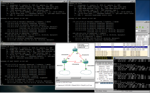
Everything up and running according to this lab. PPP on the serial links, OSPF, and full connectivity.
The router configurations:
R1:
!
version 12.4
service timestamps debug datetime msec
service timestamps log datetime msec
no service password-encryption
!
hostname R1
!
boot-start-marker
boot-end-marker
!
enable secret 5 $1$ubVD$cARJ65nFVgWPXmtFdnV9Y1
!
no aaa new-model
memory-size iomem 15
ip cef
!
!
!
!
no ip domain lookup
!
!
!
username R3 password 0 cisco
username R2 password 0 cisco
!
!
!
!
interface FastEthernet0/0
 no ip address
 shutdown
 duplex auto
 speed auto
!
interface Serial0/0
 description Link to R2
 ip address 172.16.0.1 255.255.255.252
 encapsulation ppp
 clock rate 64000
 ppp authentication chap
!
interface FastEthernet0/1
 description Connection to the 10.0.0.0/25 LAN
 ip address 10.0.0.1 255.255.255.128
 duplex auto
 speed auto
!
interface Serial0/1
 description Link to R3
 ip address 172.16.0.9 255.255.255.252
 encapsulation ppp
 ppp authentication chap
!
router ospf 1
 log-adjacency-changes
 passive-interface default
 no passive-interface Serial0/0
 no passive-interface Serial0/1
 network 10.0.0.0 0.0.0.127 area 0
 network 172.16.0.0 0.0.0.3 area 0
 network 172.16.0.8 0.0.0.3 area 0
!
ip forward-protocol nd
!
no ip http server
no ip http secure-server
!
!
control-plane
!
banner motd "Authorized access only!"
!
line con 0
 exec-timeout 0 0
 password cisco
 logging synchronous
 login
line aux 0
line vty 0 4
 password cisco
 logging synchronous
 login
line vty 5 15
 password cisco
 logging synchronous
 login
!
!
end
R2:
!
version 12.4
service timestamps debug datetime msec
service timestamps log datetime msec
no service password-encryption
!
hostname R2
!
boot-start-marker
boot-end-marker
!
enable secret 5 $1$ZxSI$l2626ABLk3aOEEJA37x5W.
!
no aaa new-model
memory-size iomem 15
ip cef
!
!
!
!
no ip domain lookup
!
!
!
username R1 password 0 cisco
username R3 password 0 cisco
!
!
!
!
interface Loopback0
 description Link to ISP
 ip address 209.165.200.161 255.255.255.224
!
interface FastEthernet0/0
 no ip address
 shutdown
 duplex auto
 speed auto
!
interface Serial0/0
 description Link to R1
 ip address 172.16.0.2 255.255.255.252
 encapsulation ppp
 no fair-queue
 ppp authentication chap
!
interface FastEthernet0/1
 ip address 192.168.20.1 255.255.255.0
 shutdown
 duplex auto
 speed auto
!
interface Serial0/1
 description Link to R3
 ip address 172.16.0.5 255.255.255.252
 encapsulation ppp
 clock rate 64000
 ppp authentication chap
!
router ospf 1
 log-adjacency-changes
 passive-interface default
 no passive-interface Serial0/0
 no passive-interface Serial0/1
 network 172.16.0.0 0.0.0.3 area 0
 network 172.16.0.4 0.0.0.3 area 0
 network 209.165.200.160 0.0.0.31 area 0
!
ip forward-protocol nd
!
no ip http server
no ip http secure-server
!
!
control-plane
!
banner motd "Authorized access only!"
!
line con 0
 exec-timeout 0 0
 password cisco
 logging synchronous
 login
line aux 0
line vty 0 4
 password cisco
 login
line vty 5 15
 password cisco
 login
!
!
end
R3:
!
version 12.4
service timestamps debug datetime msec
service timestamps log datetime msec
no service password-encryption
!
hostname R3
!
boot-start-marker
boot-end-marker
!
enable secret 5 $1$3Xc4$iVL6AWOLNG6B63VTLX9SZ0
!
no aaa new-model
memory-size iomem 15
ip cef
!
!
!
!
no ip domain lookup
!
!
!
username R1 password 0 cisco
username R2 password 0 cisco
!
!
!
!
interface FastEthernet0/0
 no ip address
 shutdown
 duplex auto
 speed auto
!
interface Serial0/0
 description Link to R1
 ip address 172.16.0.10 255.255.255.252
 encapsulation ppp
 clock rate 64000
 ppp authentication chap
!
interface FastEthernet0/1
 description Connection to the 10.0.0.128/25 LAN
 ip address 10.0.0.129 255.255.255.128
 duplex auto
 speed auto
!
interface Serial0/1
 description Link to R2
 ip address 172.16.0.6 255.255.255.252
 encapsulation ppp
 ppp authentication chap
!
router ospf 1
 log-adjacency-changes
 passive-interface default
 no passive-interface Serial0/0
 no passive-interface Serial0/1
 network 10.0.0.128 0.0.0.127 area 0
 network 172.16.0.4 0.0.0.3 area 0
 network 172.16.0.8 0.0.0.3 area 0
!
ip forward-protocol nd
!
no ip http server
no ip http secure-server
!
!
control-plane
!
banner motd "Authorized access only!"
!
line con 0
 exec-timeout 0 0
 password cisco
 logging synchronous
 login
line aux 0
line vty 0 4
 password cisco
 login
line vty 5 15
 password cisco
 login
!
!
end
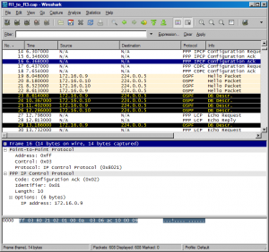
Capturing traffic on the link between R1 and R3, displaying in Wireshark. To capture traffic on a link, you just need Wireshark installed, and right click on the link you like to capture, in GNS3.
That concludes this demonstration/howto/tutorial or what you like to call it, I hope it can be interesting or helpful to someone.
Update, 2009-06-08: I see I have got some comments in kyrillic, please people, if you are not spammers aswell.. please comment in English.
4 thoughts on “GNS3: Build and configure a CCNA PPP lab using GNS3, dynamips, and vpcs”
Leave a Reply
This site uses Akismet to reduce spam. Learn how your comment data is processed.
It is useful to try everything in practice anyway and I like that here it’s always possible to find something new. 🙂
Hi there! Quick question that’s entirely off topic.
Do you know how to make your site mobile friendly?
My blog looks weird when browsing from my iphone.
I’m trying to find a template or plugin that might be able to
resolve this problem. If you have any suggestions, please share.
Appreciate it!
I just like the helpful info you supply in your articles.
I will bookmark your blog and test once more right here regularly.
I’m relatively certain I will be informed
many new stuff proper here! Best of luck for the following!